
Understanding Retaining Wall Batter Slope and Calculations
Definition and Structural Purpose of Retaining Wall Batter Slope
When engineering hardscape retaining walls, achieving vertical stability requires accounting for active lateral earth pressure. Soil naturally wants to shift downhill, exerting thousands of pounds of pressure against structural barriers. Unreinforced vertical soil faces inevitably experience shear failure over time due to gravitational forces, fluctuating moisture contents, and freeze-thaw cycles common across Massachusetts region landscapes.
A wall batter fundamentals approach introduces an intentional backward tilt toward the retained embankment. This structural geometry shifts the wall’s center of gravity backward, using gravity and the weight of the backfill material to anchor the structure into the slope. By sloping the inclination, the gravity force vector of the wall material tilts inward, actively counteracting the horizontal thrust generated by the retained soil mass. Key structural mechanisms include:
- Force Redistribution: Sloping the wall face changes the angle at which horizontal earth pressure strikes the barrier, redirecting a portion of those lateral forces downward into the foundation base rather than horizontally against the wall face.
- Base Stability Enhancement: Widening the effective functional base relative to the top minimizes localized point-load stresses and optimizes resistance against overturning forces, sliding failure, and toe crushing.
- Counteracting Natural Settling: Most structural walls settle approximately 1 degree after backfilling and soil consolidation. Building with a defined backward angle ensures that natural earth movement brings the wall toward engineered alignment rather than pushing it into a dangerous, structurally compromised forward lean.
- Friction Angle Optimization: Interlocking block units benefit from increased normal forces between courses when laid at a batter angle, enhancing shear resistance between adjacent structural layers.
For projects across Lexington, MA and Winchester, MA, implementing proper face setbacks ensures long-term structural integrity while maintaining uniform aesthetic lines across complex landscape elevations and variable regional soil profiles.
How to Calculate Retaining Wall Batter Slope Ratios
Calculating the correct retaining wall batter slope requires converting linear field measurements into accurate ratios, angles, or course setbacks. Accurate field layout prevents costly re-work and eliminates structural inaccuracies before materials are permanently set.

Field engineers and site contractors calculate batter using standard geometry principles and precise site layout tools:
- Horizontal-to-Vertical (H:V) Ratio: Expressed as horizontal setback units per vertical rise units. For example, a 1:12 ratio means a 1-inch horizontal step-back for every 12 inches (1 foot) of vertical wall rise. A 1:8 ratio represents a steeper 1.5-inch setback per vertical foot.
- Angular Measurement (Degrees from Vertical): Using trigonometry, the angle relative to plumb is calculated via the arctangent formula: $$theta = tan^{-1}left(frac{text{Horizontal Run}}{text{Vertical Height}}right)$$ A standard 1:12 setback ratio yields an incline angle of approximately 4.76 degrees from absolute vertical, whereas a steeper 1:6 batter ratio yields an incline angle of 9.46 degrees.
- Course Setback Checkpoints: Commercial installers verify layout accuracy on-site using a line level, batter board frame, and plumb reference stake. Rather than measuring row by row, field checks are typically verified every four block courses (typically 1.5 inches of setback across a 24-inch vertical rise for standard segmental systems).
- Targeted Height Calculations: To determine total horizontal setback at the top of a 6-foot wall with a 1:12 batter, multiply the vertical height by the ratio fraction (72 inches vertical height divided by 12 equals 6 inches of total backward setback).
Contractors planning projects can utilize a retaining wall slope calculator to quickly verify structural geometry before excavation begins.
Standard Batter Values Across Masonry and Block Types
Required face inclination angles vary significantly based on material composition, unit weight, internal friction angles, and interlocking mechanical designs.
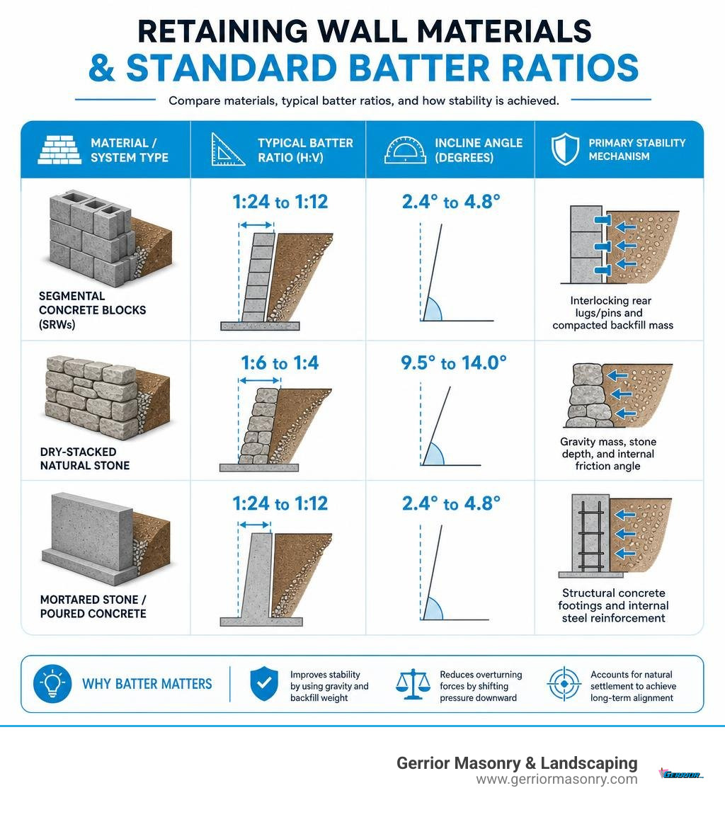
| Material / System Type | Typical Batter Ratio (H:V) | Incline Angle (Degrees) | Primary Stability Mechanism |
|---|---|---|---|
| Segmental Concrete Blocks (SRWs) | 1:24 to 1:12 | 2.4° to 4.8° | Interlocking rear lugs/pins and compacted backfill mass |
| Dry-Stacked Natural Stone | 1:6 to 1:4 | 9.5° to 14.0° | Gravity mass, stone depth, and internal friction angle |
| Mortared Stone / Poured Concrete | 1:24 to 1:12 | 2.4° to 4.8° | Structural concrete footings and internal steel reinforcement |
| Structural Heavy Rockeries | 1:12 to 1:3 | 4.8° to 18.4° | Heavy individual mass stones resting on backwards-sloped base pads |
Selecting appropriate materials for custom retaining walls in Woburn, MA or Burlington, MA dictates whether stability relies purely on gravity unit mass, structural concrete footings, or engineered geogrid soil reinforcement.
Design Best Practices for Battered Retaining Wall Construction
Impact on Wall Stability, Drainage, and Soil Reinforcement
A retaining wall batter slope cannot stabilize a hillside independently; it relies on integrated structural sub-systems, proper backfill compaction, and efficient water management to achieve long-term performance.
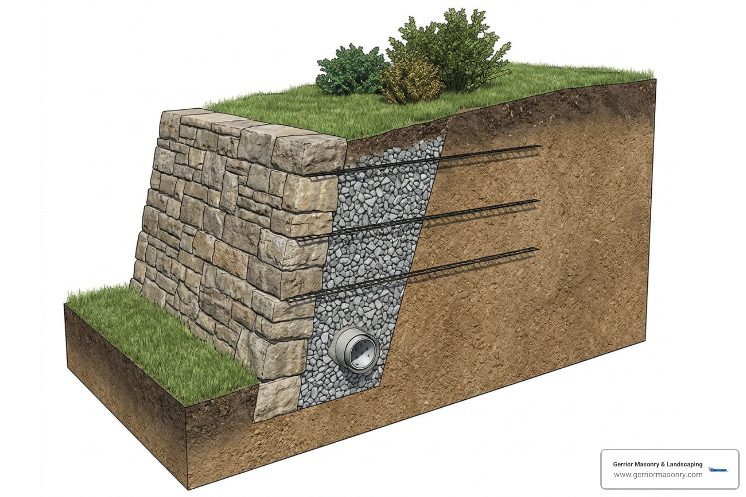
- Hydrostatic Pressure Mitigation: Trapped groundwater is the single leading cause of retaining wall displacement, sliding, and structural failure. Backfilling directly behind the wall with clean, 3/4-inch angular crushed stone creates a high-permeability drainage layer that rapidly conveys groundwater downward. Combining this aggregate layer with non-woven geotextile fabric and perforated drain pipes routes water away to daylight or dedicated drainage basins, effectively preventing hydrostatic pressure buildup behind the wall face. Review our comprehensive retaining wall stability guide to explore hydrological management principles.
- Geogrid Soil Reinforcement: For retaining walls exceeding critical height thresholds (typically 3 to 4 feet), horizontal layers of high-tensile geogrid are extended into the reinforced soil zone behind the block units. Geogrid locks with surrounding compacted aggregate to transform the retained soil mass into a unified gravity block. This engineered mechanical bond allows the wall face to maintain a stable, uniform setback angle without bowing, bulging, or forward shear movement.
- Sub-Base and Compaction Standards: Proper wall longevity depends entirely on establishing a rigid, unyielding foundation base. Base trenches must feature thoroughly compacted aggregate pads (typically 3/4-inch dense-grade crushed stone or process gravel) laid to precise depth and level. Backfill soil must be installed and mechanically compacted in maximum 6-inch horizontal lifts to achieve a minimum of 95% Standard Proctor dry density. Learn more about foundational trench preparation in our guide to retaining wall base preparation.
Common Installation Mistakes and Code Regulations
Improper wall construction often leads to costly repairs, structural displacement, or catastrophic failure during intense weather events. Avoid these common engineering and installation errors:
- Constructing Zero-Batter Vertical Walls: Building unreinforced gravity walls completely vertical (0-degree batter) without specialized structural engineering almost guarantees forward tilting over time as backfill soil consolidates and expands during freeze-thaw cycles.
- Ignoring the Foundation’s Slope: Placing base blocks on an unlevel or soft subgrade leads to uneven joint gaps, concentrated load points, differential settlement, and localized structural tipping.
- Compacting Backfill Improperly: Dumping uncompacted backfill soil behind wall units creates settlement voids, allowing rainwater to collect and exponentially increase lateral earth pressure against the block column.
- Exceeding Unengineered Municipal Height Limits: Building code regulations across local jurisdictions dictate strict height limits. Retaining structures exceeding 4 feet in total vertical height (measured from the bottom of the base pad to the top of the cap) typically require structural engineering plans, soil stability calculations, and municipal building permits.
- Encroaching on Structural Zones of Influence: Walls built within 1.5 times their height from house footings, driveways, swimming pools, or patio structures require specialized engineering analysis to prevent surcharge loads from compromising structural stability.
Professional Masonry Solutions for Massachusetts Properties
Executing precise retaining wall batter slope geometry on complex, sloped terrain requires professional experience, specialized heavy equipment, and detailed site evaluation. Gerrior Masonry & Landscaping is based near Woburn, MA and serves residential and commercial properties across Massachusetts communities such as Winchester, Burlington, and Lexington. The company specializes in masonry and hardscaping services, including patios, walkways, retaining walls, foundation repair, bulkhead replacements, chimney repairs, and commercial snow removal. With more than 30 years of experience and owner oversight on projects, Gerrior Masonry & Landscaping delivers durable, code-compliant results for complex grade changes and structural wall needs.
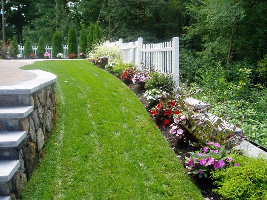
Whether you are building retaining walls on slopes in Burlington, MA or require structural repairs on existing hardscape retaining walls in Lexington, MA, Gerrior Masonry & Landscaping’s owner-supervised crews deliver long-lasting, code-compliant results.
Based on current online data and regional hardscaping benchmarks, local installation costs for structural retaining walls average:
- Segmental Concrete Block Walls: Average estimated cost of $25 per square foot of face area, with typical industry ranges extending from $50 (2x average) to $125+ per square foot (5x average).
- Natural Stone & Structural Gravity Walls: Average estimated cost of $35 per square foot of face area, with typical industry ranges extending from $70 (2x average) to $175+ per square foot (5x average).
Note: All prices mentioned are average costs sourced from publicly available internet data and are not actual Gerrior Corp prices. Project costs vary based on site accessibility, wall height, soil conditions, and engineered drainage needs.
To schedule a structural evaluation or discuss your upcoming property development needs, call Gerrior Masonry & Landscaping directly at +781-713-1225 or request an estimate online. Discover how the company’s professional custom retaining wall services protect and enhance your real estate investment.
